- 您现在的位置:买卖IC网 > Sheet目录484 > NOIV1SE025KA-GDC (ON Semiconductor)IC IMAGE SENSOR 25MP 355PGA
�� �
�
NOIV1SN025KA�
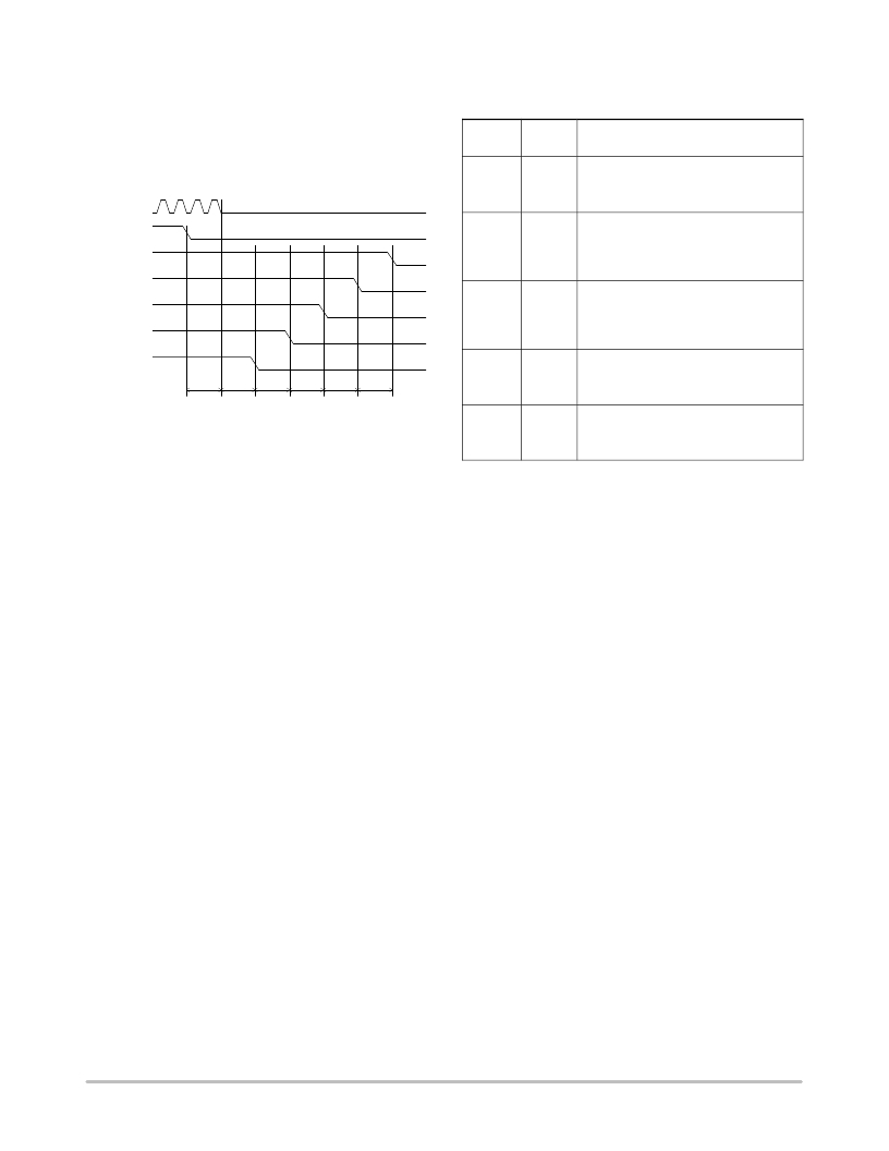
�Power-down� Sequence�
�The� timing� diagram� of� the� advised� power-down� sequence�
�is� given� in� Figure� 14.� Any� other� sequence� might� cause� high�
�peak� currents.�
�NOTE:� vdd_casc� should� be� powered� down� after�
�vdd_respd,� vdd_resfd,� and� vdd_trans.�
�LVDS� clock�
�Table� 15.� SHUTTER/OPERATION� MODE�
�CONFIGURATION� REGISTERS�
�Default�
�Address� Value� Description�
�192� [1]� 0x0� Shutter� type� selection�
�0:� Global� shutter�
�1:� Rolling� shutter�
�reset_n�
�192� [4]�
�0x0�
�Triggered� mode� selection� (global� shutter�
�only)�
�0:� Normal� mode�
�vddd_18�
�1:� Triggered� mode�
�vddd_33�
�vdda_33�
�vdd_casc�
�192� [5]�
�0x0�
�Master/Slave� selection� (global� shutter�
�only)�
�0:� Master� mode�
�1:� Slave� mode�
�other� supplies�
�>� 10u� s�
�>� 1� 0us�
�>� 10us�
�>� 10� us�
�>� 10us�
�>� 10us�
�192� [7]�
�0x0�
�Subsampling� mode� selection�
�0:� Subsampling� disabled�
�1:� Subsampling� enabled�
�Figure� 14.� Power� ?� down� Sequence�
�192� [8]�
�0x0�
�Binning� mode� selection�
�0:� Binning� disabled�
�Shutter� and� Operation� Mode� Reconfiguration�
�The� VITA� 25K� sensor� operates� in� two� shutter� modes:�
�global� shutter� and� rolling� shutter.� The� global� shutter� mode�
�can� be� combined� with� a� set� of� operation� modes,� as� described�
�Operation� Modes� on� page� 11.�
�These� modes� can� be� combined� with� subsampling� and�
�binning� modes.�
�The� shutter� and� operation� modes� are� controlled� by� register�
�192,� when� the� sensor� is� in� standby� or� idle� mode.� Table� 15�
�gives� an� overview� of� the� available� register� settings� to� control�
�the� shutter� and� operation� modes.� During� this� action,� only� the�
�fields� listed� in� Table� 15� are� affected.� All� other� settings�
�encapsulated� in� register� 192� must� remain� unchanged.�
�1:� Binning� enabled�
�Windowing� Reconfiguration�
�The� windowing� settings� can� be� configured� during�
�standby,� idle,� and� running� mode.�
�The� required� regions� of� interest� (ROI)� can� be� programmed�
�in� the� roi_configuration� registers� (addresses� 256� up� to� 351).�
�Registers� roi_active0� and� roi_active1� are� used� to� activate� the�
�desired� ROIs.�
�Default� window� configuration� (after� sensor� reset)� is� one�
�window,� full� frame� (window� #0).�
�Exposure/Gain� Reconfiguration�
�The� exposure� time� and� gain� settings� can� be� configured�
�during� standby,� idle,� and� running� mode.� Refer� to� Signal� Gain�
�Path� on� page� 29� for� more� information.�
�http://onsemi.com�
�17�
�发布紧急采购,3分钟左右您将得到回复。
相关PDF资料
NP100P04PDG-E1-AY
MOSFET P-CH -40V MP-25ZP/TO-263
NP100P04PLG-E1-AY
MOSFET P-CH -40V MP-25ZP/TO-263
NP100P06PDG-E1-AY
MOSFET P-CH -60V MP-25ZP/TO-263
NP100P06PLG-E1-AY
MOSFET P-CH -60V MP-25ZP/TO-263
NP109N04PUJ-E1B-AY
MOSFET N-CH 40V MP-25ZP/TO-263
NP109N055PUJ-E1B-AY
MOSFET N-CH 55V MP-25ZP/TO-263
NP110N03PUG-E1-AY
MOSFET N-CH 30V MP-25ZP/TO-263
NP110N04PDG-E1-AY
MOSFET N-CH 40V MP-25ZP/TO-263
相关代理商/技术参数
NOIV1SE1300A-QDC
功能描述:图像传感器和彩色传感器 VITA 1300 1.3 Mpx 150FPS Globl Shutter RoHS:否 制造商:Avago Technologies 类型:Color Sensors 工作电源电压:2.5 V 封装 / 箱体: 图象大小: 颜色读出:Color 最大工作温度:+ 70 C 最小工作温度:- 25 C 封装:Reel
NOIV1SE1300A-QXC
制造商:ONSEMI 制造商全称:ON Semiconductor 功能描述:VITA 1300 1.3 Megapixel 150 FPS Global Shutter CMOS Image Sensor
NOIV1SE1300A-XDC
制造商:ONSEMI 制造商全称:ON Semiconductor 功能描述:VITA 1300 1.3 Megapixel 150 FPS Global Shutter CMOS Image Sensor
NOIV1SE1300A-XXC
制造商:ONSEMI 制造商全称:ON Semiconductor 功能描述:VITA 1300 1.3 Megapixel 150 FPS Global Shutter CMOS Image Sensor
NOIV1SE2000A-QDC
功能描述:IC IMAGE SENSOR 2.3MP 52LLC RoHS:是 类别:传感器,转换器 >> 图像,相机 系列:* 标准包装:480 系列:- 象素大小:6.7µm x 6.7µm 有源象素阵列:768H x 488V 每秒帧数:52 电源电压:3.3V 类型:CMOS 成像 封装/外壳:48-QFP 供应商设备封装:48-QFP 包装:托盘 请注意:* 配用:4H2105-ND - HEADBOARD FOR KAC-004014H2104-ND - KIT EVAL FOR KAC-00401 其它名称:4H20954H2095-NDKAC-00401-CBC-LB-A0
NOIV1SE5000A
制造商:ONSEMI 制造商全称:ON Semiconductor 功能描述:VITA 5000 5.3 Megapixel 75 FPS Global Shutter CMOS Image Sensor
NOIV1SE5000A-QDC
功能描述:图像传感器和彩色传感器 VITA 5000 5.3 Mpx 75FPS Global Shutter RoHS:否 制造商:Avago Technologies 类型:Color Sensors 工作电源电压:2.5 V 封装 / 箱体: 图象大小: 颜色读出:Color 最大工作温度:+ 70 C 最小工作温度:- 25 C 封装:Reel
NOIV1SN025KA-GDC
功能描述:IC IMAGE SENSOR 25MP 355PGA RoHS:是 类别:传感器,转换器 >> 图像,相机 系列:* 标准包装:480 系列:- 象素大小:6.7µm x 6.7µm 有源象素阵列:768H x 488V 每秒帧数:52 电源电压:3.3V 类型:CMOS 成像 封装/外壳:48-QFP 供应商设备封装:48-QFP 包装:托盘 请注意:* 配用:4H2105-ND - HEADBOARD FOR KAC-004014H2104-ND - KIT EVAL FOR KAC-00401 其它名称:4H20954H2095-NDKAC-00401-CBC-LB-A0